10 Results
View results:
Sort by:

Wind direction plays a crucial role in shaping the outcomes of Computational Fluid Dynamics (CFD) simulations and the structural design of buildings and infrastructures. It is a determining factor in assessing how wind forces interact with structures, influencing the distribution of wind pressures, and consequently, the structural responses. Understanding the impact of wind direction is essential for developing designs that can withstand varying wind forces, ensuring the safety and durability of structures. Simplified, the wind direction helps in fine-tuning CFD simulations and guiding structural design principles for optimal performance and resilience against wind-induced effects.

The design of cross-sections according to Eurocode 3 is based on the classification of the cross-section to be designed in terms of classes determined by the standard. The classification of cross-sections is important, since it determines the limits of resistance and rotation capacity due to local buckling of cross-section parts.

Complex structures are assemblies of structural elements with various properties. However, certain elements can have the same properties in terms of supports, nonlinearities, end modifications, hinges, and so on, as well as design (for example, effective lengths, design supports, reinforcement, service classes, section reductions, and so on). In RFEM 6, these elements can be grouped on the basis of their shared properties and thus can be considered together for both modeling and design.

The classification of cross-sections is intended to determine the limits of resistance and rotational capacity due to local buckling of cross-section parts. In EN 1999‑1‑1, 6.1.4.2 (1), four classes are defined.

Table 3.1 of EN 1993‑1‑8:2010‑12 defines the nominal values of the yield strength and the ultimate limit strength of bolts. The bolt classes given here are 4.6, 4.8, 5.6, 5.8, 6.8, 8.8, 10.9. The note for this table states that the National Annex may exclude certain bolt classes. For the NA of Germany, these are the bolt classes 4.8, 5.8, and 6.8.

Structures are naturally three-dimensional. However, because it was impossible to perform calculations on three-dimensional models easily in the past, the structures were simplified and broken down into planar subsystems. With the increasing performance of computers and related software, it is often possible to do without these simplifications. Digital trends such as Building Information Modeling (BIM) and new options for creating realistic visualized models reinforce this trend. But do 3D models really offer an advantage, or are we just following a trend? The following text presents some arguments for working in 3D models.

In RFEM and RSTAB, you can use many interfaces to simplify the modeling of your structure. From background layers, to the import of IFC objects that can be converted into members or surfaces, to the import of the entire structural system from Revit or Tekla. Regardless of the performance of the selected interface, further utilization also depends on the accuracy of the imported data.

When designing a steel cross-section according to Eurocode 3, it is important to assign the cross-section to one of the four cross-section classes. Classes 1 and 2 allow for a plastic design; classes 3 and 4 are only for elastic design. In addition to the resistance of the cross-section, the structural component's sufficient stability has to be analyzed.
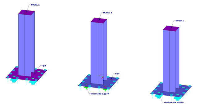
When designing column bases, high-performance anchors are often used for an anchorage. This article describes different models for a column footing and the evaluation thereof.

Prior to the analysis of steel cross‑sections, the cross‑sections are classified according to EN 1993‑1‑1, Sec. 5.5, with respect to their resistance and rotation capacity. Thus, the individual cross-section parts are analyzed and assigned to Classes 1 to 4. The cross-section classes are determined subsequently and usually assigned to the highest class of the cross-section parts. If plastic resistance is to be applied to further design of cross-sections of Class 1 and Class 2, you can analyze the elastic resistance of cross-sections as of Class 3. In the case of cross-sections of Class 4, local buckling already occurs before reaching the elastic moment. In order to take this effect into account, you can use effective widths. This article describes the calculation of the effective cross-section properties in more detail.